Well just like in real life,, my model railroad is going to disappear,, just like the railroads that I like to model.
A new house is in our very near future, there is zero room for the hobby. Right now it is in the garage, but at the new house the wife wants that back.
So what in the heck am I going to do with 1200 freight cars and 100 locos???? Plus all of the other stuff I have. I am trying to go the route of out of sight, out of mind. If I don't see it, I won't miss it.
I am trying to hold out, hoping that something good might happen,, but the window is closing and closing,, all most shut.
See ya
corner

Wednesday, October 21, 2015

Friday, May 8, 2015
Just stuff
1 .Cobalts:
Well, if you remember the post about the Cobalt switch machines, I thought about having a push button somewhere next to the turnout so I would not always have to use the DCC throttle to throw the switch.
My plan was to drill a hole through the homasote and 1/2" plywood just big enough for the push button to fit in. Then I was going to get a sheet material, either Masonite, polystyrene or aluminium and mount said push button to a piece of that. Then proceed to fasten that from underneath.
So I know you are thinking how am I going to reach the push button? I figured on using a piece of stock of some sort. I was thinking either a dowel, solid square stock or just something to make the push button "extend" to the roadbed surface to where I could push it.
So how do I camouflage it???? Paint it the same color as the scenery base color?. Maybe make it square or rectangle and paint it silver like some sort of mechanical dept box.
I just need to fiddle with this and see what works and what does not work. The main thing I was thinking about,, what happens if the spring in the push button is not strong enough to move the extension? I will just have to see what works,,, any ideas from the peanut gallery?
2. Decoders:
I now have all the decoders that I need for my fleet of locos,,, now comes the task of installing all of them. I have all the drop in decoders done, now I have 10 hard wires to do. I am going to use the TCS CN and CN-GP model for these. Heck the other night was doing 3-4 drop ins in an hour. That includes putting on kapton tape on all trouble areas and soldering the motor contacts to the boards. I do not want to go back and work on a decoder that was already installed one time,,, total pet peave.
3. Backdrop:
I do have the backdrop done, I used lightweight spackle to fill in the cracks and the screws, threw some paint on it,,, called it DONE!!!
4. Helix:
I have all material and components of the helix to start construction,,, I just need to get off my six and do something!!!! There is some final math to work on,, but I have the jist of what I want to accomplish.
Till next time, Greg
Well, if you remember the post about the Cobalt switch machines, I thought about having a push button somewhere next to the turnout so I would not always have to use the DCC throttle to throw the switch.
My plan was to drill a hole through the homasote and 1/2" plywood just big enough for the push button to fit in. Then I was going to get a sheet material, either Masonite, polystyrene or aluminium and mount said push button to a piece of that. Then proceed to fasten that from underneath.
So I know you are thinking how am I going to reach the push button? I figured on using a piece of stock of some sort. I was thinking either a dowel, solid square stock or just something to make the push button "extend" to the roadbed surface to where I could push it.
So how do I camouflage it???? Paint it the same color as the scenery base color?. Maybe make it square or rectangle and paint it silver like some sort of mechanical dept box.
I just need to fiddle with this and see what works and what does not work. The main thing I was thinking about,, what happens if the spring in the push button is not strong enough to move the extension? I will just have to see what works,,, any ideas from the peanut gallery?
2. Decoders:
I now have all the decoders that I need for my fleet of locos,,, now comes the task of installing all of them. I have all the drop in decoders done, now I have 10 hard wires to do. I am going to use the TCS CN and CN-GP model for these. Heck the other night was doing 3-4 drop ins in an hour. That includes putting on kapton tape on all trouble areas and soldering the motor contacts to the boards. I do not want to go back and work on a decoder that was already installed one time,,, total pet peave.
3. Backdrop:
I do have the backdrop done, I used lightweight spackle to fill in the cracks and the screws, threw some paint on it,,, called it DONE!!!
4. Helix:
I have all material and components of the helix to start construction,,, I just need to get off my six and do something!!!! There is some final math to work on,, but I have the jist of what I want to accomplish.
Till next time, Greg
Saturday, March 14, 2015
Cobalt DCC switch machines
After building the yard, I knew I wanted a postive throw for all the turnouts. There are plenty of ways out there, slide switch, Tortoise, caboose ground throws, and hand made springs made from wire/staples.
So after much thinking and the lack of doing a whole bunch of wiring I decided to use the new Cobalt switch machines made by DCC Concepts out of Australia.
You can see in the picture below the size is smaller than the Tortoise, they even have a provision for mounting them sideways for control of crossing gates and semaphores.


So after much thinking and the lack of doing a whole bunch of wiring I decided to use the new Cobalt switch machines made by DCC Concepts out of Australia.
You can see in the picture below the size is smaller than the Tortoise, they even have a provision for mounting them sideways for control of crossing gates and semaphores.
After reading up on these I realized that the wiring is super easy. Two wires from the DCC buss, and one wire from the frog,, Bam,, you have a turnout with powered frog!!! There is even more contacts to allow for control from a panel via a push buttom or toggle switch. And you can even power signals/LED's from these machines.
Programming these machines is a snap. You slide the little white switch to the left, to the "set" postion. Select the turnout number you want to control on your throttle and press the button, then once done, slide back to the right. "run" position. That is all you need to do. I use Digitrax with the DT402D. So I started by moving the little white switch to the "set" position, then I selected the Switch button on the throttle, then entered a number, then pressed either T or C. Slide the switch back to the right(run) and that is all that I did. And now I have a switch machine that I can control by using the DT402D throttle.
You are probably asking how does it know what polarity to make the frog? I asked the same thing too. I found out by using a test light on the frog and opposing rail I could check it. If it was wrong, I would just swap the wires out that go from the buss to the machine.
These machines are a snap to install,, I like them, plus it saves on all the extra wiring that you have to do with other machines. I try to make sure that when I position the machine the Thrown and Closed position are the same on the actual track switch. So if you select Throw on the 402D the turnout is aligned for the diverging route and if you select Closed, the turnout is lined for the straight route.
There are some switch machines that I am not able to rotate because of benchwork members, so I need to figure out how to change the Thrown and Closed position.
I have installed 12 so far, I plan to control these with the 402D and push buttons. Even further down the road I will use JMRI Panel Pro to control them also. I choosing to add push buttons on the fascia so you can still throw the turnouts without the main throttle. I have an idea to use a piece of square styrene next to the turnout that is numbered to match the push button on the fascia. I had also thought about fabricating something to fasten the push button next to the turnout, probably drill a hole next to the turnout. So that would keep your attention on the layout and not having to look at the fascia. Any ideas out there???
Over all I am really satisfied with there little machines from the land down under. And,,, the are cheaper than the Tortoise cousin called the SMAIL ( Slow Motion Actuator with Integrated Logic)
Wow look two blog posts in one day. I am on a roll. So hopefully I can keep going on this roll and have the layout progress quicker than it has in the past.
See ya later,
Greg
Backdrop redux
The original backdrop was 1/8" Masonite fastened directly to the sheetrock walls in my garage. Over the years silverfish have eaten through the Masonite in spots. The Masonite that I used was off the old layout, so I had plenty of joints to tape and float. With the temperature changes in the garage caused the joints to crack and peel, so I had to think of a new way to do it.

I was going to use 1/4" Masonite this time,, but the big box stores in my area were out of it, so I found some 1/4" underlayment. I also decided to fasten 3/4" material on the sheetrock first before hanging the
underlayment. The brown spots you see in the picture is where the silverfish attacked the Masonite and sheetrock.


I was going to use 1/4" Masonite this time,, but the big box stores in my area were out of it, so I found some 1/4" underlayment. I also decided to fasten 3/4" material on the sheetrock first before hanging the
underlayment. The brown spots you see in the picture is where the silverfish attacked the Masonite and sheetrock.
After hanging the underlayment I was really satisfied with the way it came out. You can see in the picture above that I ran the 3/4" material below the bottom of the backdrop, I did that so I would have a surface to secure the new benchwork to.
Here is one coat of paint. The blue that I chose was a match to the blue on the printed backdrop from Realistic Backrounds. I took a section to the local big box and had the paint department match the blue. On the previous layout I had cut the sky out from the prints and just affixed the pictures to the backdrop once the paint had cured for a couple of days.
So I still need to fill the holes and fill the seams, then apply the final coat of paint. I am ready to get the new sections of benchwork up,, so I can start laying the new trackage.
I thought about asking for help from the forums and other resources for a track plan to use. The area is question is going to be 1'-6" x 14'. Any ideas out there?
Well that is it for now, more to follow.
See ya, Greg
A head ache but well worth it!!
While surfing eBay I came across the new release of the Intermountain F7 in Milwaukee Road,, thinking,,Hmmmmm.
So I pulled the trigger!! 2 F7A's and 1 F7B. I am could see the other kinds of consists in my minds eye, GP30-F7B-GP9,,, GP9-F7B-F7A. Well you get the idea. To make sure that these units would fit my era I did some internet research and found these were still around in 1980 and maybe a little longer.
I received the decoders in the mail first, and I was excited to get the locomotives. So now I have the locos and decoders,, thinking this looks easy,, solder 4 wires in the A's and 2 wires in the B's,, then BAM done.
Wrong,, ended up being a little head ache. These decoders are the DN166i1d, which are the new series of chips from Digitrax. To make a long story short,, you need to apply kapton tape to the frame anywhere where the motor or the decoder could possibly come in contact with, or the locomotive will not function properly.
The first A unit,, well that was frustrating,, first the wanna be MT 1015 was hard to get out, then proceeded to fall apart, ( no where did that little spring go???!!!!???). No Kapton tape the first try,, decoder took programming,, but nothing from the motor. I hooked up test leads straight to the decoder,, hmmm motor works now,, what the hey!!!!
After applying kapton tape to the inside of the motor frame where the motor might touch and putting tape in the bed where the decoder sits,, BINGO,, we have movement!!! So the A took about 4-5 times of dis-assembly to get right. The B unit took 3 times,, and the other A unit took one time!!!! See I can learn.
I would not have known to kapton tape the entire universe if it were not for Allen Heimsoth, and various internet forums.

Well I have more updates to post, just need to sit down in front of the laptop to get them done.
My next big project is to replace the backdrop in the torn down area. Might get that done this coming week, see ya'll later
Greg
So I pulled the trigger!! 2 F7A's and 1 F7B. I am could see the other kinds of consists in my minds eye, GP30-F7B-GP9,,, GP9-F7B-F7A. Well you get the idea. To make sure that these units would fit my era I did some internet research and found these were still around in 1980 and maybe a little longer.
I received the decoders in the mail first, and I was excited to get the locomotives. So now I have the locos and decoders,, thinking this looks easy,, solder 4 wires in the A's and 2 wires in the B's,, then BAM done.
Wrong,, ended up being a little head ache. These decoders are the DN166i1d, which are the new series of chips from Digitrax. To make a long story short,, you need to apply kapton tape to the frame anywhere where the motor or the decoder could possibly come in contact with, or the locomotive will not function properly.
The first A unit,, well that was frustrating,, first the wanna be MT 1015 was hard to get out, then proceeded to fall apart, ( no where did that little spring go???!!!!???). No Kapton tape the first try,, decoder took programming,, but nothing from the motor. I hooked up test leads straight to the decoder,, hmmm motor works now,, what the hey!!!!
After applying kapton tape to the inside of the motor frame where the motor might touch and putting tape in the bed where the decoder sits,, BINGO,, we have movement!!! So the A took about 4-5 times of dis-assembly to get right. The B unit took 3 times,, and the other A unit took one time!!!! See I can learn.
I would not have known to kapton tape the entire universe if it were not for Allen Heimsoth, and various internet forums.
Well I have more updates to post, just need to sit down in front of the laptop to get them done.
My next big project is to replace the backdrop in the torn down area. Might get that done this coming week, see ya'll later
Greg
Tuesday, March 3, 2015
Yup, it's gone....
Well since I posted last, I managed to do some demolition.


After looking at my backdrop closer, I found an insect problem, SILVERFISH!!. So to combat that, I am going to redo the backdrop also. I plan on tearing down the existing 1/8 masonite, if I would have known about these pesky insects, I would not have screwed the masonite directly to the wall.
So I plan to place 1x2's on the studs in order to " stand off" the new 3/16" masonite. That should reduce the surface area for the insects to attack, I also treat the affected area before re-construction.
I figure to tear down, re-install, bed,tape, float in one day, then primer and paint the next,,, two days. Easy peasy. Then the next step is construct the new helix,, and I will leave that for another post.
See ya later,
Greg

After looking at my backdrop closer, I found an insect problem, SILVERFISH!!. So to combat that, I am going to redo the backdrop also. I plan on tearing down the existing 1/8 masonite, if I would have known about these pesky insects, I would not have screwed the masonite directly to the wall.
So I plan to place 1x2's on the studs in order to " stand off" the new 3/16" masonite. That should reduce the surface area for the insects to attack, I also treat the affected area before re-construction.
I figure to tear down, re-install, bed,tape, float in one day, then primer and paint the next,,, two days. Easy peasy. Then the next step is construct the new helix,, and I will leave that for another post.
See ya later,
Greg
Thursday, February 19, 2015
Well it has been awhile
Howdy all!!
Well I have been gone for a good while, but I am back with a vengeance!!! I have been on mission acquiring the material needed for a serious upgrade. Also accomplished during this mission was getting a loco buffer/USB. After many head scratching sessions, emails to all corners of the earth....I finally was able to get it installed and working on Windows Vista. Now I just have to enter all loco data into JMRI to make my roster.
I was able to get the following items, along with other stuff...(freight cars!!!) I was hoping this day would come, to prepare I have been buying supplies here and there,, spikes,,, wire,, solder, etc etc etc. Because once I start,, I don't want to be in holding siding because the train master did not plan and purchase properly!!!
Homasote
1/2" sanded plywood
1/8" masonite
Code 55 track
Cobalt switch machines w/DCC
Various tools to accomplish the job
I plan on tearing out the existing trackwork along the wall that the industrial section is attached to. Remove all 3/4" plywood and replace with the 1/2" plywood. I also plan on painting the homasote before one screw is used to fasten in into place.
Here is picture of what there is now. The trackwork right now is code 80, which will be changed over to code 55.

What you do not see in this picture is where the helix used to be. Let's just say the helix is no longer with us,,( moment of silence).
The plan is to re-construct the helix using double track super elevated Kato unitrack. I am going to try a different method this time,, I going sandwich 1/8" masonite together and use all-thread supports and clear 3/8" PVC for spacers. After having my first helix being single track,, I am now going to double track. The goal is to have two trains of the 86' auto parts cars pass each other with ZERO issues. We will see what we will see.
Well that is all for now, hopefully some more pics of work in progress to come.
See ya,
Greg
Monday, March 17, 2014
Still here
Howdy all!!!
I am still here.. Just been doing little here, a little work there. I have been building the code 55 turnouts that are going to replace the code 80 ones that are currently in the industrial area.
Instead of using the Fast tracks quick sticks. I thought about a way to make a tie jig. After remembering a thread I read a while ago. The original poster made a comment about using flex track to make a tie jig. So I used his idea, but I used sectional track.

After checking everything to see if it would fit, I applied the Pliobond to bottom of the rails and then set the turnout on the ties. What you don't see it the weights that set on the rails to make sure the glue made good contact and set properly. I let the assembly sit overnight.

Here is a #6 turnout that was constructed in a fast track assembly fixture placed on the tie fixture. The ties I used are Micro Engineering Turnout Ties.

Now getting the turnout out of the fixture was a little tricky. I had to remove one the pieces of track that I used for the fixture. Seems the ties were caught under the foot of the rail. I am thinking that if I remove the rails and just use the ties as the fixture,, the completed turnout will come out much easier.

I trimmed the ties to proper length by using a Atlas turnout as a visual reference. I know the throw bar looks huge, well it is because I used Fast Tracks 1/32" HOn3 PC ties. The N scale ones would not allow for a hole to be drilled for the wire that numerous switch machines use. I also wanted something sturdy and not flimsy. Once painted I don't think it will be that noticeable.

Well there ya have it, I need to make some more so I can have plenty when I begin the removing the code 80. Now I just need to make the decision to either stay with the industrial section I have now, or come up with a different plan. Anybody have any ideas? The is roughly 14' x 20" to work with.
The area available is from the piece of Homasote by the helix to the wall in back by the curve. The piece of plywood you see in foreground is no longer there. But,,, I could put it back. Who knows.

So till next time,
Adios,Greg
Wednesday, February 12, 2014
New videos from the public relations department of the WBTR
Seeing that I just got my new loco in, Milwaukee Road 156, the bi-centennial unit that Kato/Kobo did, I wanted to show it in a couple of videos.
The first video was taken with a regular video camera, I have no idea how it came out smashed together like it is. The second video I used my handy dandy smartphone, seeing that it takes video in HD.
Ya'll can be the judge,, now remember be nice,, I am not a oscar winning anything.LOL
Thanks for looking!!
See Ya, Greg
The first video was taken with a regular video camera, I have no idea how it came out smashed together like it is. The second video I used my handy dandy smartphone, seeing that it takes video in HD.
Ya'll can be the judge,, now remember be nice,, I am not a oscar winning anything.LOL
Thanks for looking!!
See Ya, Greg
Thursday, January 30, 2014
Completion of the Helix remodel
After all the demolition, I was able to sand the areas that needed it. I also came across some areas that I used screws in. They were fine before since the cork covered them, but now that I don't plan on using cork I need to grind down the heads. So I loaded a grinding stone in the Ol' dremel and away I went. I know I made a point of wearing saftey glasses, grinding particles can and will get everywhere. I deal with that in my job as a welder for Caterpillar Inc.
After all of that was done, I used a tack cloth to clean all the dust and particles from the sub-roadbed so that the adhesive caulk would adhere better. This loctite caulk is pretty good, real easy to use and it grabs pretty quick.


I remember last time, I soldered three sections of flex together for the helix. That was a pain, so this time I decided to solder two sections together. Before soldering, I cut one tie off each end of the flex track section. This worked great, because of the 20" radius that I was using did not require the rail to move that much.


After all of that was done, I used a tack cloth to clean all the dust and particles from the sub-roadbed so that the adhesive caulk would adhere better. This loctite caulk is pretty good, real easy to use and it grabs pretty quick.
I made transitions from cork to make sure I was at the proper elevation. This was fairly easy with the use of a surfoam, sanding block and a powered detail sander. Out of all three,, the surfoam tool worked the best.
I remember last time, I soldered three sections of flex together for the helix. That was a pain, so this time I decided to solder two sections together. Before soldering, I cut one tie off each end of the flex track section. This worked great, because of the 20" radius that I was using did not require the rail to move that much.
I made sure to pay attention to the smoothness of the soldered joint, any bumps would not be good. I had scrap steel laying around that I use for weights,, worked great.
I made sure the rails were in line and also that the rail joiners were centered.
Here you see the completed solder joint.
After I laid the first two piece section,, I measured to see how much rail is cut off on the ends to make joints line up. Worked out to be 14mm. So I fabricated the two piece flex track sections, cut the right amount off, applied the adhesive caulk and a track laying I did go!!!!
There are some sections that I needed to add more supports to. You can see here, there is no support for the joint area of the sub-roadbed. You can see the added support in the picture prior to this section of text.
While laying the track,, I noticed that I did not have to solder the connections between the two piece sections. The adhesive caulk and new rail joiners did the trick,,nice flowing curved joints!! I am so relieved that helix works MUCH better. Before I had to watch it all the time, now I can run a train in there and not even worry about it.
Well that is it for now, I plan on taking some videos of trains traversing the helix. That will be a little later. I work weekends,, so maybe Tuesday next week,, who knows.
Thanks for looking, Have a great one, Greg
Monday, January 27, 2014
Helix remodel
You know people say, that if you do not make mistakes you are not learning or trying. Well I learned alot.
My helix has given me constant fits!! So I decided to rip up all the track. I am even removing the cork too. I had used a acrylic based adhesive caulk for laying my track,, worked really well, to the point of making it a royal pain in the rear to remove.
The reason for track removal, is because when I had laid the track I put the adjustable ( sliding) rail on the outside. Which makes the gauge too wide. Yay me for being stoopid. Well now I am going to fix it! only been a couple of years dealing with the PITA.
When I started the deconstruction of the helix I thought I would be able to save the track. I guess I was naive in thinking that. Nope, no way, ain't going to do it,,,etc. So,, I decided to remove everything, say goodbye mr track and mr cork, Bye Bye. Which is not too bad,, the helix takes about 27 pieces of track. Minus the 3 on top,, and about 5 pieces I saved,, not too bad. I need to get the other helix built also.
I used a couple different tools for the removal process. Putty knife,,nope. Xacto chisel blade,,,no way. 16" floating knife, used in taping and bedding sheetrock, that no workie either. Finally I decided to use a 1 1/2" chisel. Nice and sharp is the key here. An easy touch, and BLAMMO the track and cork come off easy. Which leaves me with less work to do with a sander to make it all smooth.

Here you can see the tie imprint in the caulk,,note to self,, don't use that much next time.!!!

When I was cutting out the roadbed for the helix, I made sure I had centerlines for the cork. As you can see they are still there which will make the track re-laying easy peasy

After I get all the roadbed up, I plan on sanding the plywood roadbed smooth to get rid of any remaining glue and or cork. When I get the new track laid, I will post some more pictures and also a video of the first train using the new helix.
Anyways,, that is all for now.
See Ya, Greg
Wednesday, November 6, 2013
Fond Du lac upgrade?
After about a month of layout non-activity, I am toying around with upgrading/changing my industrial area. Right now the trackage is all cd80 Atlas with #6 turnouts, laid right on 3/4" plywood.
I came up with an idea using a combination of cd 55 #6 turnouts made from a Fast Tracks fixture, and #5,#7 turnouts from Atlas. The flex track is Atlas also.
When I do attempt to do this, I will have to remove all the cd 80 track and then lower the benchwork by 1/2" to allow for the use of homasote.


So I could either use the mixture of the different size of turnouts like I did in the previous pictures or I could use just one size. If I were to choose one size it would probally be the #6. Since I feel the #5 is too small and the use of a #7 would just be a space eater. The #6 would be fixture assembled seeing that I already have the fixture on hand.
They would look like these. On the two turnouts you see here, the darker ones are the ones that I built my self. I used Krylon Camoflauge Brown to paint the quick sticks tie assemblies.

Here is one where the ties are not painted,the turnouts sure do operate smoothly.

Well that is all for now,, so we will see what we will see in the coming weeks.
Thanks for reading!!
I came up with an idea using a combination of cd 55 #6 turnouts made from a Fast Tracks fixture, and #5,#7 turnouts from Atlas. The flex track is Atlas also.
When I do attempt to do this, I will have to remove all the cd 80 track and then lower the benchwork by 1/2" to allow for the use of homasote.


I see some areas that can be fixed, in the picture below I could have used all RH turnouts to avoid the snake. I know the picture is not the great ,but you see what I mean

So I could either use the mixture of the different size of turnouts like I did in the previous pictures or I could use just one size. If I were to choose one size it would probally be the #6. Since I feel the #5 is too small and the use of a #7 would just be a space eater. The #6 would be fixture assembled seeing that I already have the fixture on hand.
They would look like these. On the two turnouts you see here, the darker ones are the ones that I built my self. I used Krylon Camoflauge Brown to paint the quick sticks tie assemblies.

Here is one where the ties are not painted,the turnouts sure do operate smoothly.

Well that is all for now,, so we will see what we will see in the coming weeks.
Thanks for reading!!
Friday, October 11, 2013
Weathering,,,if you really want to call it that
After reading forums, magazines and just talking to friends I decided to try my hand at weathering again. After yesterdays attempt, I think the WBTR is going to invest numerous wash racks and pressure washers,,,Then I won't have to weather anything!!! LOL
These pieces of rolling stock were the first ones I ever weathered back in 2003, and you can tell it!! I mostly used a india ink wash, some oil pigments and some floquil instant weathering spray.


 Here is the current as of 10/10/2013 weathering project. I used acrylic craft paints, acrylic artist medium, and weathering powders by Bragdon Enterprises.


These pieces of rolling stock were the first ones I ever weathered back in 2003, and you can tell it!! I mostly used a india ink wash, some oil pigments and some floquil instant weathering spray.
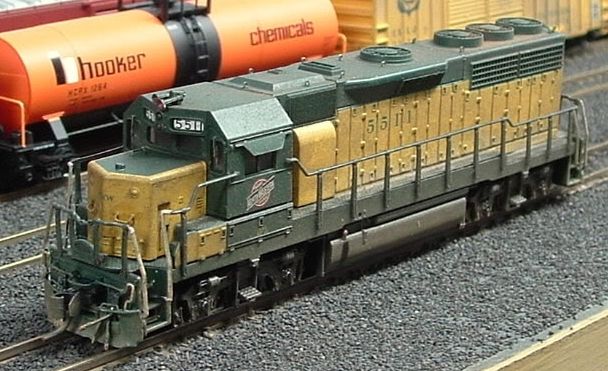
This is the first locomotive I did. The loco started out as a super detail project, but then after seeing that yellow paint did not match up, I decided to weather it with some Floquil paints sprayed from my airbrush, I also used weathering powders for the first time.
This was my first ever detail and weather job together. If you have go to the BLMA website, this loco is in the detailed models section, page 2. After Craig posted it, my head got so big,,, I could not wear any hats.LOL
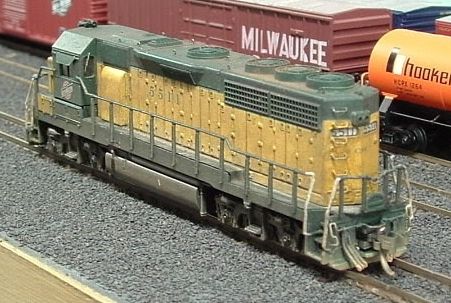
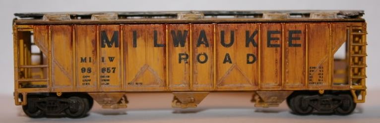
These following models were done by using weathering powders, acrylic artist medium, and acrylic craft paints for washes.


The Milwaukee Road covered hopper seemed like a good place to practice. This is before I heard of fading the paint and distressing the lettering.
Here is a PWRS Covered hopper, once again before I new about fading and distressing the lettering and the logo. I think I came out ok. Some freinds of mine say it looks real good.
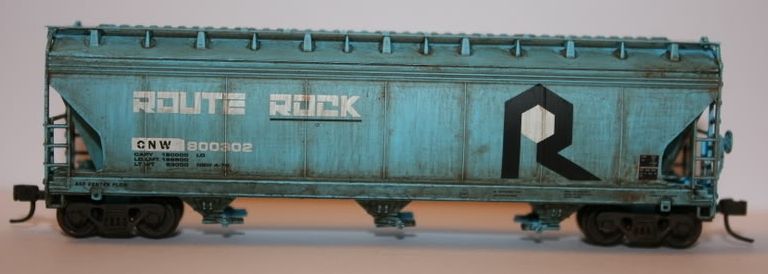
I did some boxcars while I was waiting for the washed on the covered hopper to dry. Nothing better than actual real sunlight for pictures. I was happy with the way they turned out.
 Here is the current as of 10/10/2013 weathering project. I used acrylic craft paints, acrylic artist medium, and weathering powders by Bragdon Enterprises.
The fade wash came out ok. before I put on the fading wash, I took a pink eraser and distressed the lettering and logo. And then the fade wash. Some people apply the fade with a airbrush, I used a brush,, I wish my compresor was up,,but nope, it is sleeping with the fishes.

I next used acrylic washes and powders. Me thinks I should have waited for each phase to dry/cure, I bet it would have came out better.
I used raw umber on the trucks, looks alright. I feel once you have the right pigments/paints you can do anything.

You can really see the "rust" weathering powders in these two pictures. I was trying to go for a scrape from the door, also a textured appearance at the track on the bottom where grime, dirt and rust would gather.

Well there you have it, I am no artist, heck I did not even stay at a Holiday Inn Express last night.
I think my collection is going to be coming out of the wash rack/paint shop everyday.LOL
Thanks for looking.
Wednesday, October 9, 2013
Video tour of the WBTR
Well one more post for today, a video tour of the WBTR, and some other videos. I hope ya'll enjoy!
Here are some other videos that I have.
Here are some other videos that I have.
Here is a video from version 4 of the WBTR. Boy that FP 45 sure sounds nice!!!
Just a short little video less than a minute of a CNW concrete train.
And last video, this is a layout that I help a friend with. He is modeling the Indiana Harbor Belt. Great layout!!!!
Thanks for watching!!!
The current version, version 5
Well here we are at the current version of the layout. The staging and the helix have remained the same, but the visible trackage has changed.


While moving the pieces around and figuring out what was going where, I thought of a ops plan,,well sort of. For example one train could depart from staging, traverse the helix then arrive in the industrial area. The train could either serve the customers or it could continue to the main yard. The train could also park on the passing track, pull the industrial yard tracks, then yard the train it brought up from staging. I really have not thought about ops just yet, that is going to be a separate blog posting.
I use photographic backdrop from Realistic Backgrounds . I purchased these back in 2003, and I still have them. Now there are more companies that are doing the same thing, bigger and different scenes. So you just have to search for ones that you like.


In this picture you are looking north or westbound. Like in previous versions of the layout I decided to call the area Fond Du Lac. Or I also thought of the Fond Du Lac Industrial Zone. Also in the picture you can see that I have the backdrop taped and floated. I also painted the backdrop a blue color that was matched from the photo backdrops that I use.

To the right in this picture is where the yard is going to go. I think I have plenty of room.

Another shot of the yard area, this picture also gives a nice perspective on the distance between the real level and the staging level.

This is where I originally thought about putting the helix, but plans have changed since that. I am going to come back to the opposite wall by 14'-6". So when the new addition is done, the layout will be in a "G" shape. So when walking between the helices to enter the layout, that will be a 4' aisle way.

In version 5, I swapped locations of the yard and industrial area. So now the yard and engine facility are on the longest wall because I wanted a nice sized yard. So that required me to move the industrial area right next to the helix.

The buildings you see in these two pictures are not in their permanent home. Some are, some aren't. Some days I just move them around and see how that works, some days I don't even go out to the layout. But since the weather is getting better, I will be going out there more.
While moving the pieces around and figuring out what was going where, I thought of a ops plan,,well sort of. For example one train could depart from staging, traverse the helix then arrive in the industrial area. The train could either serve the customers or it could continue to the main yard. The train could also park on the passing track, pull the industrial yard tracks, then yard the train it brought up from staging. I really have not thought about ops just yet, that is going to be a separate blog posting.
I use photographic backdrop from Realistic Backgrounds . I purchased these back in 2003, and I still have them. Now there are more companies that are doing the same thing, bigger and different scenes. So you just have to search for ones that you like.

You can see the Realistic Backgrounds products in the picture to the left and behind the boys. I don't know how that cowboys jersey slipped by me,LOL The city scapes I cut with a knife and straight edge to see how well it worked as opposed to just leaving the sky attached as you can see in the steel mill scenes.
So now we progress with more pics

Here is the main yard. I can bring in an 11' foot train into the A/D track.

South end of the yard and the pocket track.

When I had originally laid the yard, I realized that the tracks were too close together. This picture was taken when I had re-laid the throat trackage. The track pictured by the backdrop is an industrial track.

Just a shot of the SOO local pulling out of the yard.

Here we have the yard power doing some classification work.

After re-laying the south end, I worked on the north end. I had posted a design thread on multiple forums about designing a engine facility and it morphed into a combination yard throat/ facility design thread. With other modelers and friends giving suggestions I came up with what you see here. I used was the Santa Fe yard throat design from David Barrow's Cat Mountain and Santa Fe. All turnouts in the picture are Atlas #7 code 55.

The engine facility.

A nice aerial view of the facility and throat trackage, came out pretty nice.

You can see the yard and facility in this shot looking south.
This is where I am now. Time to install turnout control and install additional track power feeders. I am also thinking about making a section of the front facility track the new programming track. There will be a toggle switch to switch from main track power to the programming track.
Right now I am just running trains to make sure the yard works flawlessly.
Thanks for reading and following along!
Subscribe to:
Posts (Atom)